- PAGE SETTINGSClick on the gear to simplify view
- Settings

Lesson Plan
Tutorial Video(s)
What You’ll Need
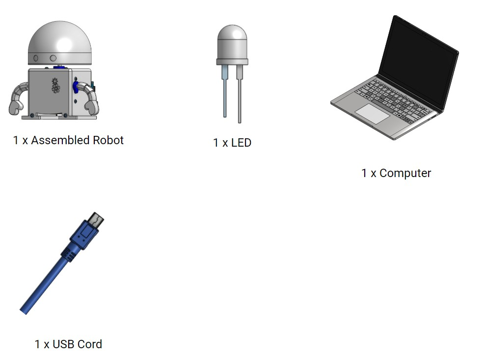
Before we get started, let’s make sure that we have all the parts.
Overview
In this lesson, we’ll be introducing computer engineering and software engineering by connecting your LED to your robot’s brain and programming the brain to control the LED. We’ll be covering:
- How to connect a light to your robot’s brain.
- How the robot’s brain and personality work together to make the light blink on and off.
Getting To Know Your Robot’s Brain
Just like the human brain, your robot’s brain has hundreds of wire pathways that are connected together to help your robot store information and make decisions. Each of these wire pathways in your robot is a circuit. As we learned in the previous lesson, a circuit is just another way of describing a pathway for electricity to flow.
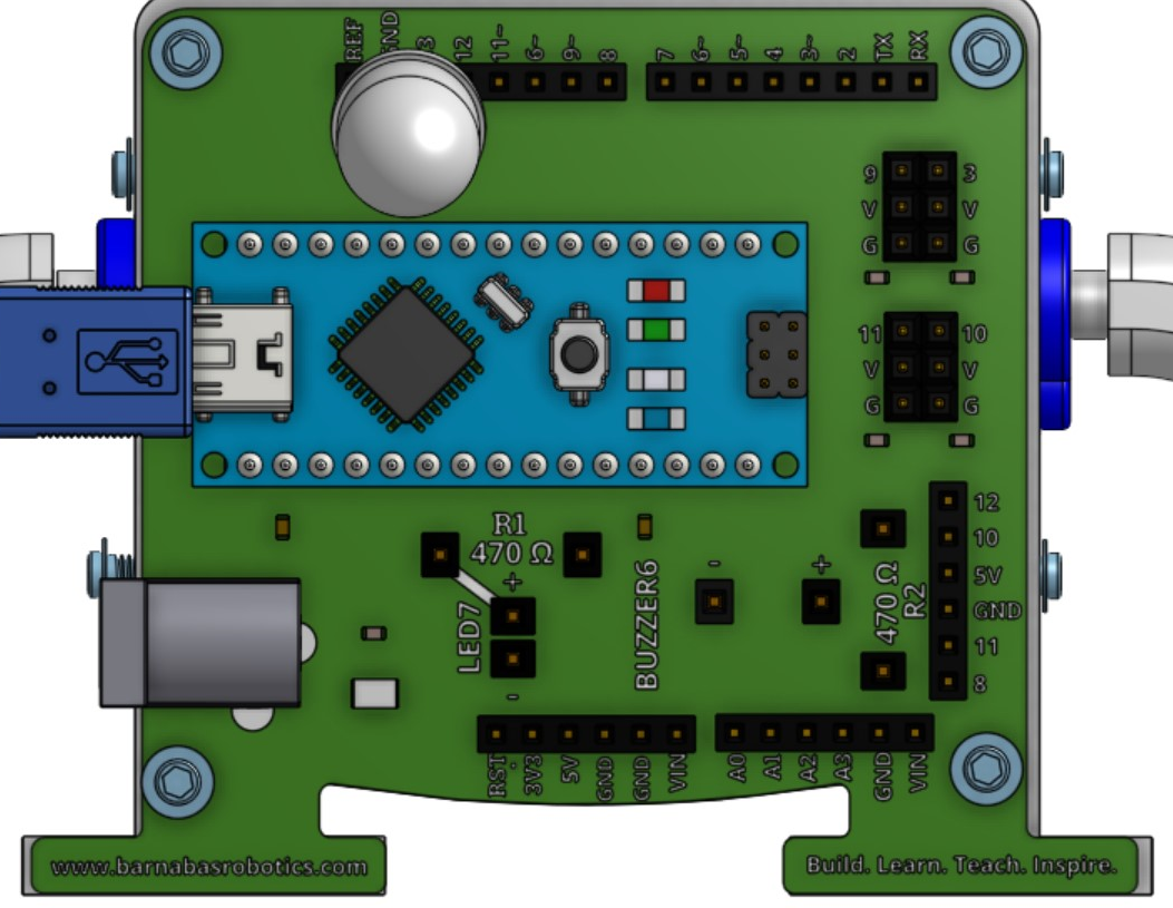
Your robot’s brain is called the Barnabas Noggin.
For the most part, the Barnabas Noggin is already designed and built, but you’re going to be adding a few electrical pathways (or circuits) for your robot to have special functions. In this lesson, you’ll not only be connecting your LED to your brain, but you’ll be learning how to control the LED through code!
Connecting Your LED To Your Robot’s Brain
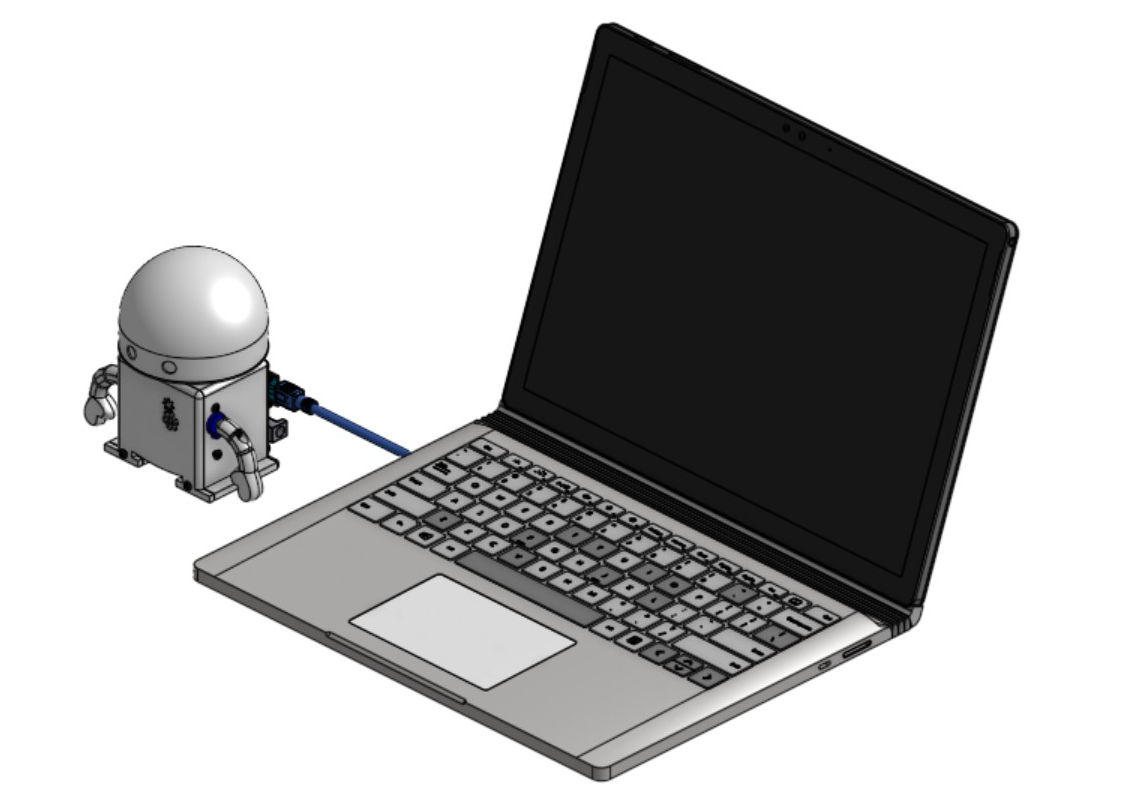
First, if you haven’t already done so, go ahead and remove your LED and resistor from the Barnabas Noggin. Make sure your Barnabas Noggin is plugged into your computer via the USB cord. The red light on your Barnabas Noggin should be on.
Next, we need to connect the LED to the Barnabas Noggin. In the previous lesson, the LED would stay on as long as the Barnabas Noggin had power. This time we want to connect it in a way so that it only turns on if the Barnabas Noggin has code to tell it to turn on. In order to do this, we need to connect the LED to a special place, called a pin.
A pin on the Barnabas Noggin is a power source that can be turned off and on depending on its computer code.
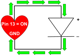
Observe the circuit below that includes a pin connection, LED and a resistor.
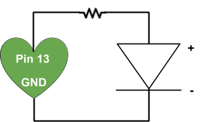
If Pin 13 turns on, it will be as if there is a battery in the circuit. This would cause electricity to flow, causing the LED to turn on.
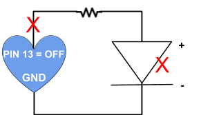
If Pin 13 turns off, it will be as if the battery is shut off. This would cause electricity to NOT flow, causing the LED to turn off.
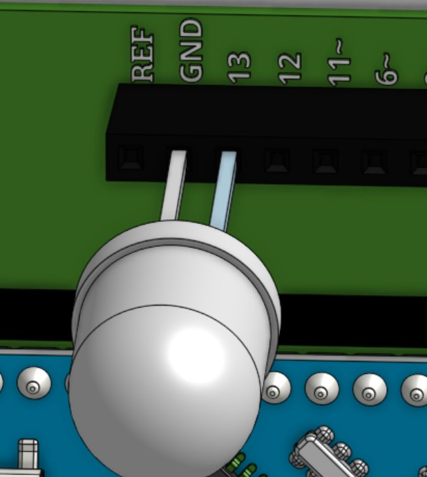
Let’s now build this circuit.
- Connect the positive (+) end of your LED to pin 13 on your Barnabas Noggin and the negative (-) end of the LED to the GND right next to it.
- We’re done! You may be asking, “What about the resistor?” Well, there is a tiny resistor already built into the Barnabas Noggin, so that part is already done for you!
Introduction To Coding
It’s now time to get your robot to turn your LED on and off in your circuit. To do this, we first need to create instructions to send to your robot’s brain to tell it to turn the LED on. The process of creating instructions for your robot is called computer programming or software engineering. The actual set of instructions that we create is called computer code.
What is Computer Code?
Let’s go back to our human brain analogy. A human brain without any information stored in it wouldn’t be able to accomplish any of the functions that we do every day (e.g. walking, running and talking). Likewise, a computer needs to have information in it to make a robot function. As humans, we learn instructions so that we can accomplish tasks like washing our hands or making a sandwich. We learn these tasks by reading, listening or observation. Computers learn by receiving computer code, written by humans.
How Computer Code Works
These instructions will be followed by the computer in the order that they are written. When the computer gets to the end of the list of instructions, it goes back to the beginning of the list of instructions and starts over.
Sending Computer Code to the Noggin
After you’ve created your computer code, you’ll need to send the code to the Barnabas Noggin so that it can actually be stored in the brain. This process is called uploading.
The LOOP do Block
It’s time to start coding! Go ahead and open your IDE

Let’s first learn the basics of your IDE. In your IDE, your code will be made up of a series of blocks that snap together like puzzle pieces.
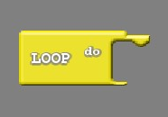
The first block to introduce is called the “LOOP do.” The “LOOP do” will house all of the other blocks used in your code. It is like the outside cover of a book, which houses all of its pages. The computer reads the pages (i.e. code blocks) within the “LOOP do” block from the beginning to the end. When it gets to the end, it starts back at the beginning and begins again. This process repeats forever as long as your Noggin has power.
Note: You can only have one “LOOP do” in your code.
How to Add a Block
Let’s add a “LOOP do” block to our code!
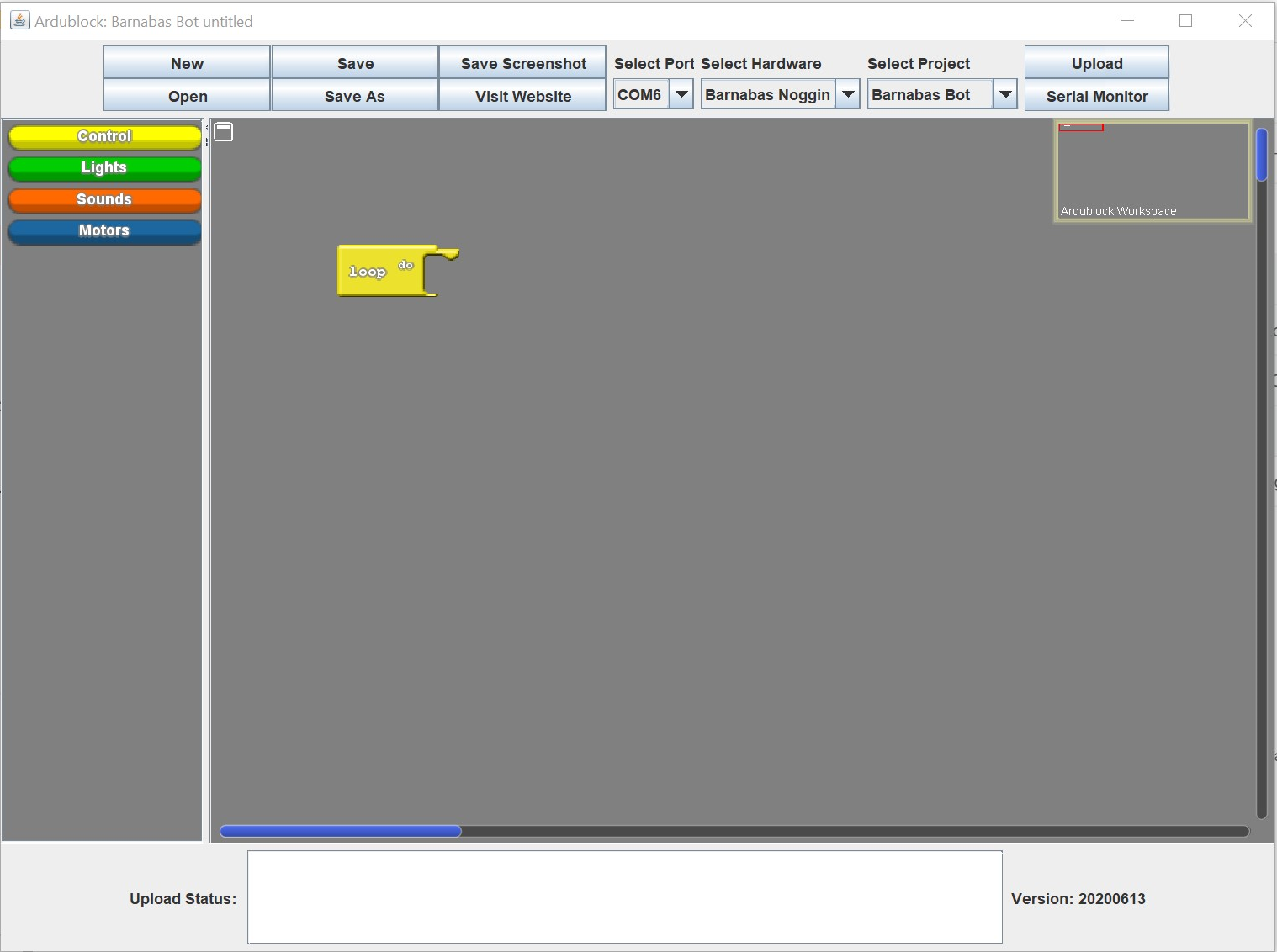
- Find the colored buttons on the left side of your screen labeled “Control,” “Lights,” “Sounds,” and “Motors.” Click on the yellow “Control” button to the left.
- After you click on the yellow “Control” button, you’ll see a menu of yellow blocks open up. Click (and hold down) on the “LOOP do” block and drag it into the large area to the right of the colored buttons. When it is in the large area, release the click.
How to Delete a Block
There may be times when you’ll need to delete blocks of code. For example, if we have multiple “LOOP do” blocks in our code (remember your code can only have one “LOOP do” to work), we need to get rid of the extras.
Let’s practice by deleting the “LOOP do” block from our code.
- Click (and hold down) on the “LOOP do” block and drag it over to the tabs on the left side of the window.
- Release the click and the “LOOP do” block should disappear.
Now that we know how to delete a block that we don’t want, let’s go ahead and bring in a “LOOP do” block again so that we can continue building our code.
Turn The LED On
We are now ready to program our LED to turn on.
- Click on the green “Lights” button on the left side of your screen.
- You’ll see a menu of green blocks open up. Click (and hold down) on the “LED” block and drag it immediately to the right of the “Loop do” block so that it clicks into the “LOOP do” block.
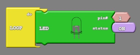
Notice the “pin#” and “status” pieces on the right side of this block. The “pin#” setting allows you to specify the pin that you want to control. The “status” setting allows you to turn your pin on and off. Be default the “pin#” is set to 1. Because our LED circuit is connected to Pin 13, we need to change it to 13. Follow these instructions:
- Click on the “1”
- Replace “1” with “13” by typing it in.
- Press Enter
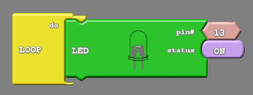
The “ON” setting tells us that this block will be turning pin 13 on (i.e. giving it power). Let’s leave that as is for now since we do want our LED to turn on!
Our First Upload
We are now ready to upload our code to our robot. Before doing so, let’s check a few things.
1. Confirm power.
Make sure that the USB cable is connecting your Noggin to your computer. A red light on your noggin should be on.

2. Set your hardware.
Make sure to select “Barnabas Noggin” under the “Select Hardware” drop down. This tells your computer what type of robot brain you are trying to communicate with.
3. Set your port.
The port is like an address for your Barnabas Noggin. If it’s not set correctly, your computer won’t know where to send the code that you just wrote!

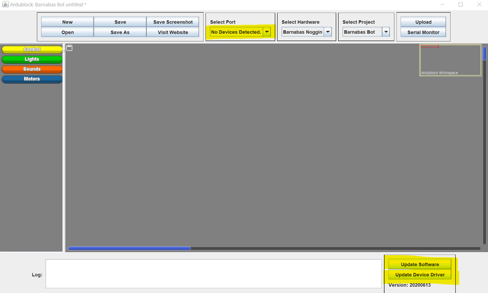 You may need to wait a few minutes if it’s the first time that you’ve connected your Barnabas Noggin to your computer. If you’ve waited for more than 5 minutes, try clicking on “Update Device Driver” on the bottom right. This installs some software that helps your computer find your Barnabas Noggin.
4. Upload.
Now click “Upload” at the top of the Ardublock window to begin the upload process.
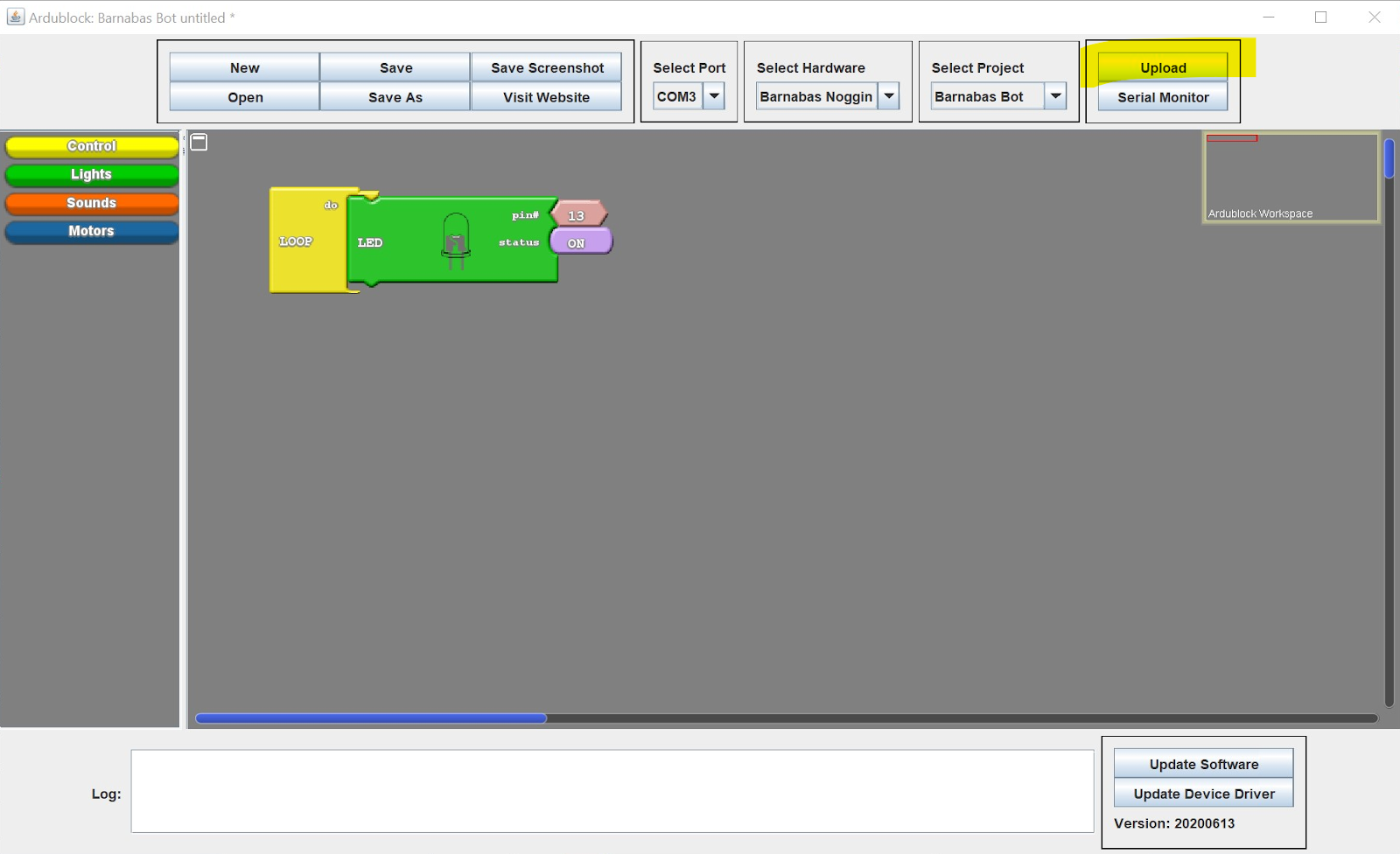
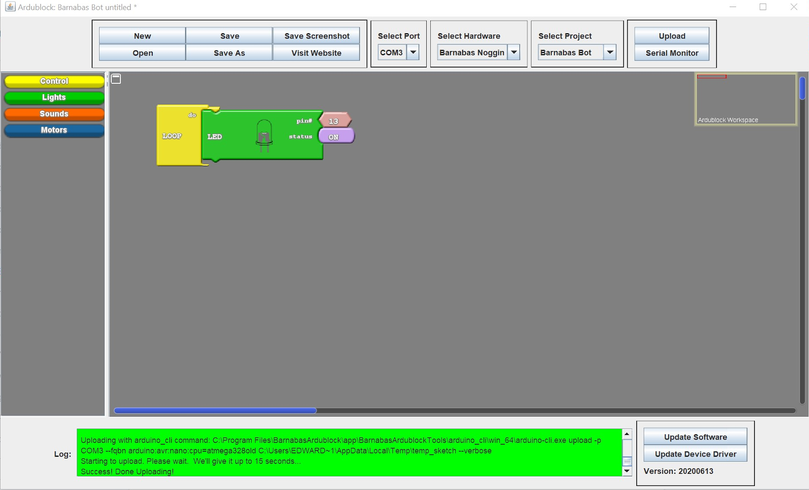
It will take a little time, but once it finishes, the window on the bottom should turn green. Once upload completes, your LED should turn on!
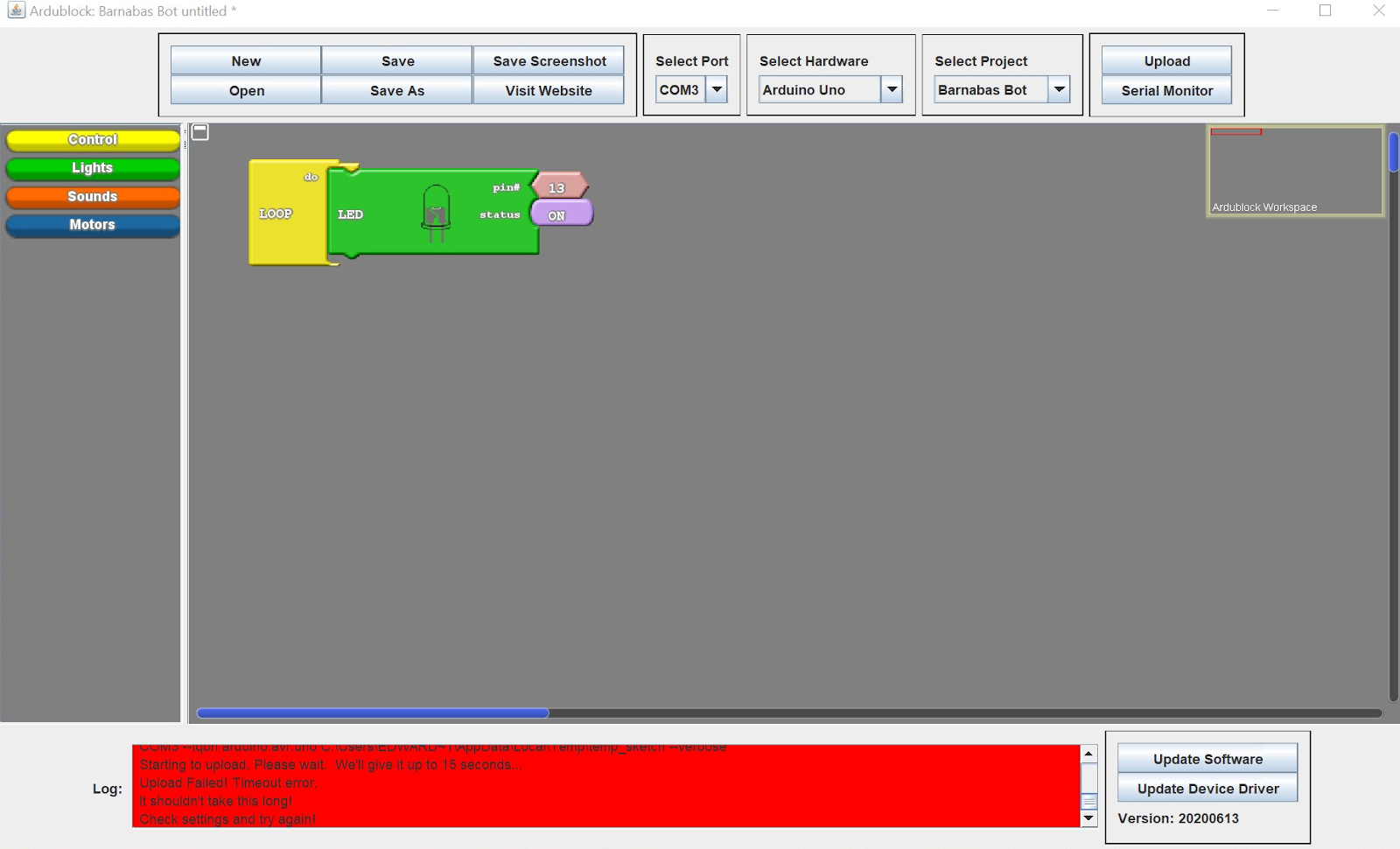 (1) Make sure that “Barnabas Noggin” is selected under “Select Hardware”. (2) Make sure that a port is selected. (3) Click “Update Software” and allow the update to finish.
Turn The LED Off
Great job! Now, let’s change our code so that our Noggin turns the LED off.
- Move your mouse to the right of “ON” until you see a triangle show up.
- Click on that triangle
- Select “OFF”
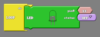
After changing the status, upload the code again so that the Barnabas Noggin gets the new instructions. Once upload completes, your LED will turn off!
The Blinking Light Challenge
Now it’s time for the big challenge, blinking the LED. To do this, we can start by placing another LED block into our “LOOP do”.
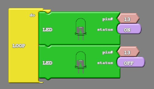
Remembering what we have learned about how code works, the first block will turn the LED on, and the second block will turn the led off. This will happen in order and then repeat over and over again. You might think that this would give us a blinking light right? Well actually, the code is correct, but we can’t tell that it’s correct. The reason has to do with speed. Each block is an instruction, and the Barnabas Noggin processes instructions super fast. That is one of the benefits of computers. They process instructions much faster than humans! The downside is that sometimes they work so fast that we can’t even tell what they are doing.
Try uploading the code and see what happens. You should see the light just seem to be on all the time rather than blinking.
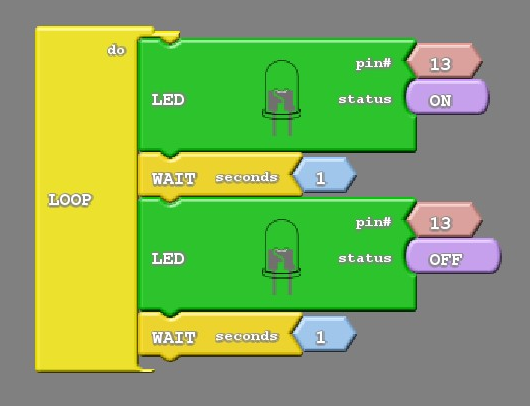
Now there is a way to slow our code down deliberately. We will use the wait block. The wait block will stop code from progressing forward until a certain amount of time has elapsed. It is the amount of time that the robot brain DOES NOT execute any new instructions.
Put a 1 second wait block after both LED blocks and upload again. You should see a blinking light!
Practice!
Try the following exercises to get the hang of playing with the light.
- Try writing a program that turns your light on for 2 seconds off for 2 seconds and then repeats forever
- Write a program that turns your light on for 0.5 seconds, off for 0.5 seconds, and then repeats forever.
Challenge!
- Write a program that makes your light blink as fast as possible!
- Write a program that blinks slowly a few times and then blinks fast a few times!
Bonus Activities
Want to add a second LED and/or learn how to make secret codes (Morse Code) with your LED? Check out the bonus activities!