- PAGE SETTINGSClick on the gear to simplify view
- Settings

Lesson Overview
Disciplinary Core Ideas
- ETS1.B: Developing Possible Solutions: Tests are often designed to identify failure points or difficulties, which suggest the elements of the design that need to be improved. (3-5-ETS1-3)
- Science is a Human Endeavor: Most scientists and engineers work in teams. (4-PS3-4)
Learning Target(s)
Technical Skills
- Understanding physical limitations; range of motion (angles), power consumption
Life Skills
- Perseverance
Essential Question(s)
- What can limit a robot’s movements?
- Do we program the servo motors by giving them angles of position, or angles of motion? What is the difference between the two?
Key Vocabulary
- Servo
- Limits
- Modulation
Depth of Knowledge Levels Addressed
- Level 1: Recall and Reproduction
- Level 2: Skills and Concepts
- Level 3: Strategic Thinking and Reasoning
- Level 4: Extended Thinking
Barriers to Learning
- Poor understanding of range of motion, angle position vs. angle of motion
- Inability to distinguish between known blocks in Ardublock
- Poor understanding of previous coding exercises i.e. blinking light and buzzer
Anticipatory Set
- Students will learn to code their motors to move the extremities of the robot and achieve repeated motion
Independent Practice
- Wiring a single motor using the breadboard
- Using code to experiment with the range of motion of the motors as well as the necessary sequence for repeated motion to occur
Final Assessment, project or product
- Getting the robot to wave or shake its head
Lesson Materials

Lesson Plan
Step 1: How Does The Servo Motor Work? (5 min)
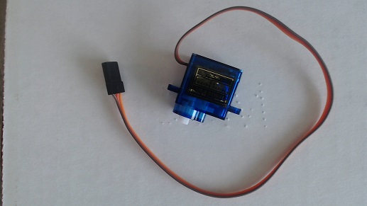
Above is a picture of a servo motor. There are multiple types of servo motor, however the important characteristic of our servo motors is that they can only move in half a circle, 180 degrees.
Each servo motor has three wires attached to it: an orange wire, a red wire and a brown wire. If you consider the previous components, the LED and buzzer, you may remember that each of them only needed two wires to function. The main difference between the motor and our previous components is how much current the motor requires. The motor constantly needs 5V fed to it in order to function, where the buzzer and LED only needed 5V intermittently. The motor has two wires dedicated to pumping current in and out of the motor, these are the red (5V) and brown (GND) wires. In our robot human analogy these wires would be the veins. The orange wire, on the other hand, is responsible for sending a signal to the motor which will tell the motor to move. This wire would be more analogous to the nerves that extend across our bodies, carrying signals from our brain to the muscles.
Vocabulary
- Servo Motor: The servo motors our robot uses are 180 degree rotation servo motors, meaning they only have a range of motion of about half a circle. The servo motors require much more power than the LED or the buzzer, which necessitates a third wire attached to the motor. The motor has one wire dedicated to ground (GND), one dedicated to power (5V), and one dedicated to receiving a signal from the Arduino.
Step 2: Connecting The Motor (10min)
Start by drawing the circuit schematic below:
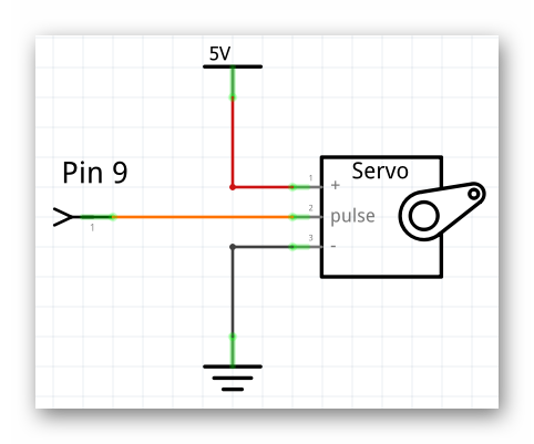
The first image is a more official looking schematic, however it may be difficult for your students to understand what this schematic is saying.
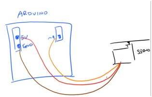
While the following schematic looks more primitive, it will probably seem less abstract to the students.
In general I would advise drawing the schematic on the right, however if you are looking to challenge your students you can draw the more abstract schematic on the left.
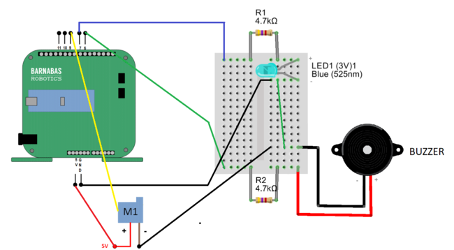
In order to attach our motors to the breadboard we will need to augment the servo motor wires. You will need three jumper wires, preferably yellow, red and black, to correspond with the orange, red and brown wires of the servo motor. Place one end of each of the jumper wires into the ends of the motor wires, being sure to color code the wires appropriately; yellow->orange, red->red, black->brown.
Just like it was recommended in past lessons, try having your students collectively build a breadboard diagram of the circuit based on the schematic you have drawn. Below is a diagram with all of the components we currently have attached to the robot:
Step 3: Getting Our Robot To Wave (45 min)
To control the servo motor we will need the servo block, located in the pins tab:
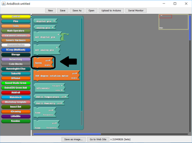
Upon closer inspection you will see, like some of the other blocks we have used to this point, the servo block expects two input values:
The first, unsurprisingly, refers to the pin the motor has been placed on. In our case this is pin 9. The second is called the angle. The angle refers to the position that the motor will move to, not the total amount of motion that will take place. For example inputting an angle of 90 will not make the motor move 90 degrees, it will move to whatever position is associated with 90 degrees, no matter how near or far that is from the motor’s current position.
While programming the servo motor, don’t forget to consider its physical limitations. The servo motor is capable of rotating in half a circle, 180 degrees. Because of this the angle from 0 to 180 are valid inputs for the servo block. You are welcome to try other angles, it will not damage the motor to do so but you should not expect the motor to behave itself if you do.
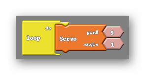
With all that being said I think it is time to experiment. Just have your students pick an angle they would like to try and upload their code. What happens? Many of your students will claim they say movement, however they can not get the movement to repeat, even after uploading their code again. After giving them some time to experiment and note this behavior recommend to the students that they change the angle before uploading again, and to be more precise they should pick an angle that is drastically different than their current angle. At least 30 degrees different. They should notice that the motor moves to a new position, and once again stays there.
This is a good time to reiterate that the angle chosen does not move the motor by that much, but rather moves the motor to the position associated with that angle.
Can we do better than this? Can we do better than repeatedly uploading code to the robot in order to get constant motion from the robot? If fact we can, and doing so won’t require knowledge of any new blocks. Much like the set digital pin and tone blocks we can use delay in tandem with the servo block to create repeated effects, such as what is shown below:
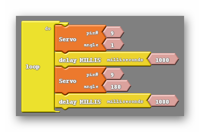
The code above will move one of the robot’s motors back and forth over the span of two seconds.
Vocabulary
- Servo Block: The servo block is the block used to control the servo motors on the robot. It requires two things, the pin the motor is located on and the angle the motor is meant to move to. The angle can accept any number but the physical limitations of the servo motor limit the effective range from 0 to 180.

REFLECTION
- If the motor has previously been set to 20 degrees and is then set to 90, how many degrees does the motor move?
- Why are there three wires attached to the servo motor and what do each of them do?