- PAGE SETTINGSClick on the gear to simplify view
- Settings

Lesson Overview
Disciplinary Core Ideas
- Define a simple design problem that can be solved through the development of an object, tool, process, or system and includes several criteria for success and constraints on materials, time, or cost. (3-5-ETS1-1)
- Connections to Engineering, Technology, and Applications of Science: Influence of Engineering, Technology, and Science on Society and the Natural World Engineers improve existing technologies or develop new ones. (4-PS3-4)
Learning Target(s)
Technical Skills
- We will learn to design our robot’s body using Computer-Aided Design (C.A.D.).
Life Skills
- Communicating Effectively
- Problem Solving
- Time Management
- Preparation
- Inspiration
Essential Question(s)
- What challenges can Computer-Aided Design (C.A.D.) present for a beginning user?
- Why would someone use a computer for design rather than creating a blueprint by hand?
- What is perseverance?
- Why is it important to practice perserverance?
- Why should we take the opportunity to teach others what we know?
- Does teaching help others? ourselves?
Key Vocabulary
- Dimensions
- Plane
- Axis
- Rotation
- Translation
- Zoom
- Isometric
Depth of Knowledge Levels Addressed
Barriers to Learning
- Minimal understanding of 3-D concepts and geometric solids
- Minimal understanding of abstract perception
- Minimal understanding of angles (0°, 90°, 180°, 270°)
- Difficulty visualizing the possible axes of a 3-D object
Anticipatory Set
- Students play with a physical geometric solid - rotating and translating the objects on an axis in varying degrees and talking about how the perception of the object changes
- Set the norm for frustration tolerance
Independent Practice
- Students work on their individual files to put the robot together and to design the front plate
Final Assessment, project or product
- Completed at the end of the next lesson is a customized Barnabas Bot with a production ready STL and PDF file.
Lesson Materials

Lesson Plan
Review
- Review the four parts of a robot and how it relates to the human body
- What is the difference between design and build?
Step 1: What Is CAD? (15 minutes)
Computer-Aided Design (or CAD) is used by engineers across many disciplines. Specifically, when building a robot, CAD is used by a mechanical engineer to create the frame or body of the robot. CAD software allows us to create very precise designs with perfect lines and shape, that would be difficult to sketch by hand. CAD is also advantageous because the blueprint is stored digitally and can be accessed on most devices anywhere in the world at a moment’s notice. With an electronically-stored blueprint, an engineer can then create the design using a machine and material of their preference. Our robots will be 3D-printed using plastic.

Step 2: CAD Walkthrough (45 minutes)
Preemptive Vocabulary
- L-CLICK: Clicking with the left button of your mouse or mouse pad.
- R-CLICK: Clicking with the right button of your mouse or mouse pad.
Onshape is a very convenient CAD tool. It uses your internet browser and saves all your files to a cloud server. Because of this we do not have to worry about installing software or misplacing files. After creating your own Onshape account follow the instructions below:
-
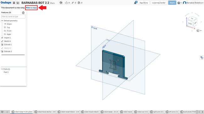
Once you are logged into OnShape, open the Barnabas-Bot Template file.
-
Create a copy by L-CLICKing on “Make a private copy”
-
Name the project: “BARNABAS-BOT 2.3 [YOUR NAME]. Make sure to choose “Public”.
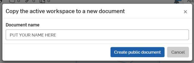
-
Once you do this, a new project should open up, which will be a copy of the original project, but with this new name.
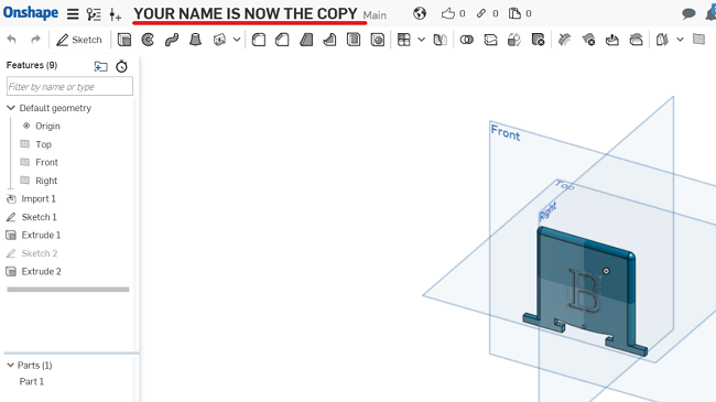
-
You are now ready to customize your robot’s body!
OnShape Basics
Before diving into things you will need to become somewhat proficient with OnShape’s tools. Here are a few tips on how to move stuff around in OnShape:
- Open the file “robot body front plate.”
- Rotation
- Method 1: L-CLICK on arrows in the cube on the top left to rotate the entire perspective.

- Method 2: R-CLICK on a part and move the mouse.
- Method 3: L-CLICK on the “FRONT, BACK, LEFT, ETC.” on the cube on the top left.
- Method 1: L-CLICK on arrows in the cube on the top left to rotate the entire perspective.
- Translating a part (moving it up, down and side to side)
- Method 1: Hold down CTRL and R-CLICK on the part to move it around.
- Method 2: L-CLICK down using the SCROLL button to move it around.
- Zooming
- Use the scroll button to zoom in and out.
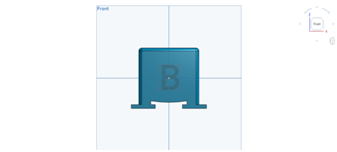
- Go to “FRONT VIEW.”
- Press “F” to fit the part into your screen. This is called, “ZOOM TO FIT.”
Writing on Your Robot’s Body
Now we will begin the design of our own custom robot. This starts by customizing the text on the front plate (chest) of your robot. In this section we will learn both how to enlarge and how to change text:
-
Open the “robot body front plate” file in OnShape.
- Change the size of the text
- Double L-CLICK on the “B” until you see a number pop up on the right side of the screen
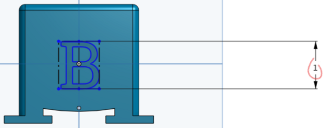
- Change the number to a larger number (like 2 or 3). The B should be larger now!
- Change the value to “0.5”. The B should be smaller now!
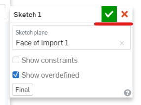
- Click on the green check mark to save your changes
- Double L-CLICK on the “B” until you see a number pop up on the right side of the screen
- Move the location of the text.
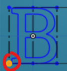
- R-CLICK on the “B” and L-CLICK on “Edit Sketch 1…”
- L-CLICK on one of the 4 blue corners (they are kinda small, you might need to zoom in) of the rectangle around the B and drag the blue rectangle up and down
- Click on the green check mark to save your change
- Change the text.
- R-CLICK on the “B” and L-CLICK on “Edit Sketch 1…”
- R-CLICK on the “B” again and L-CLICK on “Edit Text”
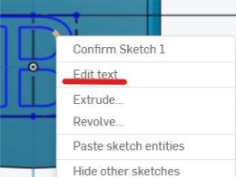
- Now change the text to “C”. Click on the green check mark and see if it changes!
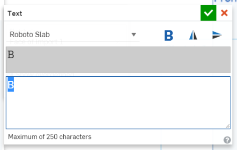
- Now change the text to “BARNABAS”. You’ll see that it doesn’t fit on the robot face. How can you make it fit? (Change the size of the text to 0.3 or less)
- Click on the green check mark and see if it changes!
- Now change the text to whatever you want!
- It can be a single letter, or many letters. Play with different sizes. Make sure that all of the text fit on the robot! Remember to click on the green check mark to save your changes! Make sure to keep the size of the text larger than 0.3 so that it comes out well during printing!
What if I lose the dimensions?
What if I lose the the WHOLE LETTER B?
Putting Your Robot Together
This is where you will put all your robot’s body parts together and create the final file that you will share with us. You will need to drag and rotate your robot’s pieces into place. Keep in mind that you shouldn’t be concerned with perfection. Regardless of mistakes in the assembly file, the parts will be 3D printed appropriately. Follow along with the steps below to assemble your robot:
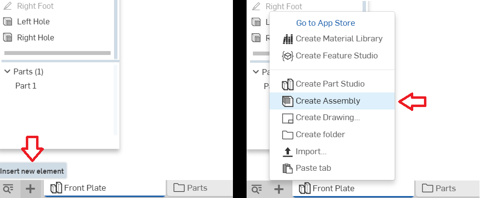 Create an assembly file
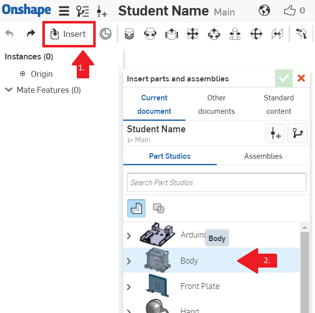
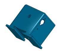 Insert the front plate
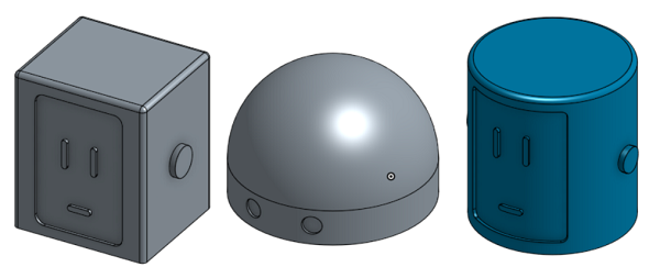 Insert one head
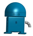 Insert your left arm and align it
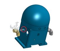 Insert your right arm
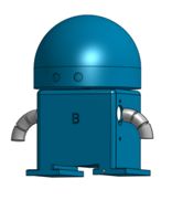 Line it up
Vocabulary
- Dimension: A measurable extent, such as length, depth, or height.
- Axis: An imaginary line an object rotates around. Ex. the Earth has an axis that goes through its north and south pole. It rotates around this axis once every day.
- Plane: A flat, two dimensional object that extends infinitely far.
- Rotation: The movement of an object around its axis or center.
- Translation: The movement of an entire object in a direction. The object is not altered or rotated in any way.
- Isometric: Of or having equal dimensions. An isometric view, for example, will show all three dimensions equally.


REFLECTION
- What does CAD stand for?
- What advantages does CAD offer as opposed to designing by hand?
- Describe, in your own words, an assembly.