- PAGE SETTINGSClick on the gear to simplify view
- Settings

Lesson Overview
Disciplinary Core Ideas
- Define a simple design problem that can be solved through the development of an object, tool, process, or system and includes several criteria for success and constraints on materials, time, or cost. (3-5-ETS1-1)
- Connections to Engineering, Technology, and Applications of Science: Influence of Engineering, Technology, and Science on Society and the Natural World Engineers improve existing technologies or develop new ones. (4-PS3-4)
Learning Target(s)
Technical Skills
- We will learn to design our robot’s body using Computer-Aided Design (C.A.D.).
Life Skills
- Setting Goals
- Preparation
- Perseverance
Essential Question(s)
- What challenges can Computer-Aided Design (C.A.D.) present for a beginning user?
- What is perseverance?
- Why is it important to practice perserverance?
- Why should we take the opportunity to teach others what we know?
- Does teaching help others? ourselves?
Key Vocabulary
- Production
Depth of Knowledge Levels Addressed
Barriers to Learning
- Minimal understanding of angles (0°, 90°, 180°, 270°)
- Difficulty visualizing the possible axes of a 3-D object
Anticipatory Set
- Students play with a physical geometric solid - rotating and translating the objects on an axis in varying degrees and talking about how the perception of the object changes
- Set the norm for frustration tolerance
Independent Practice
- Students work on their individual files to put the robot together and to design the front plate
Final Assessment, project or product
- Rotating and inserting the additional parts to the body
Lesson Materials

Lesson Plan
Review
- What does C.A.D. stand for?
- Can you explain what 3-D means?
- What advantages does CAD give us as opposed to designing by hand?
Step 1: Creating An Assembly File (10 -15 minutes)
With the robot assembled we have the opportunity to generate a drawing of the robot. The drawing consists of four 2 dimensional views of the robot, each from a different angle. The overall drawing resembles something closer to a traditional blueprint and will be included with your robot’s 3D printed parts when those are shipped to you.
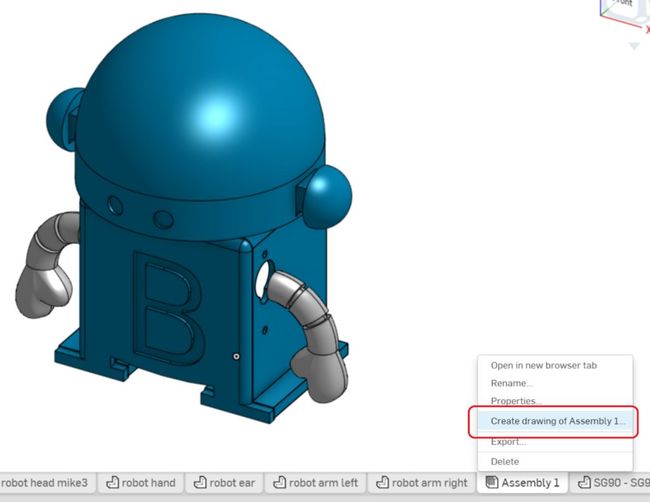
- R-CLICK on the assembly file tab that you just created
-
L-CLICK on “Create drawing of … “
-
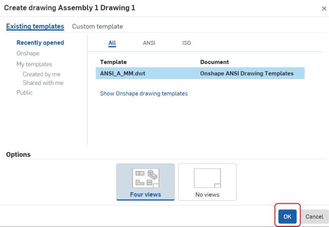
A screen will pop up. Make sure that “Four views” is selected under “OPTIONS”, and L-CLICK on “OK”
-
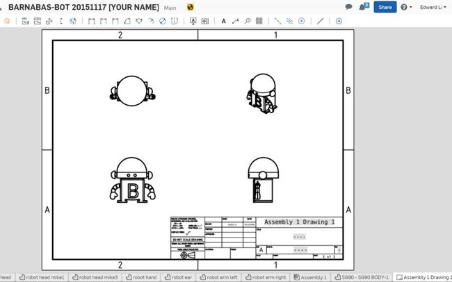
A drawing will be automatically created.
-
Double L-CLICK on the text boxes to edit the text. Write your name as well as your robot’s name.
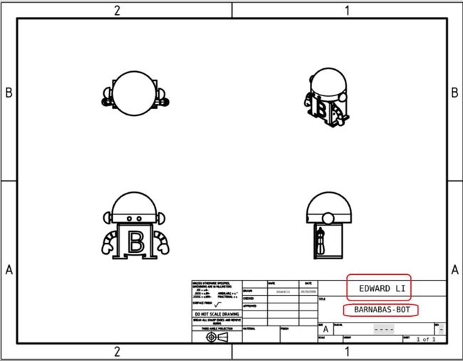
- You are done!

Share your robot with us!
This step is necessary if you would like us to 3-D print your robot for you.
- Directions on how to shares file on OnShape
- Share it with the following email address: “info@barnabasrobotics.com”
Once you share it with us, we will provide a confirmation within 24 hrs. Now just sit back and relax as we start putting your robot kit together!


REFLECTION
- What constraints or challenges did you have to keep in mind in designing your robot?
- Can you describe the four views in the drawing using last week’s vocabulary?
- Describe, in your own words, an assembly.
- Why should we take the opportunity to teach others what we know?
- Does it help others? Does it help ourselves?